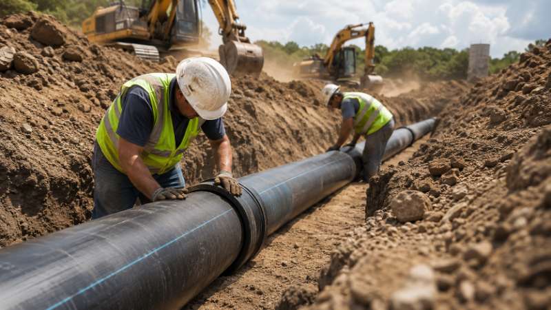
HDPE pipe installation requires more than digging a trench and laying pipe. Done correctly, it delivers infrastructure that performs for 50 years or more under Australia's demanding soil, climate, and regulatory conditions. Done poorly, it creates failures that cost water authorities and contractors far more than the original project.
This guide covers the complete underground installation process for HDPE pipe — from site preparation and trench design through to pressure testing and failure prevention — all referenced to Australian Standards. Whether you're specifying for a water authority project or managing installation on a civil construction site, this is the technical reference you need.
Viadux supplies HDPE pipe and fittings to water authorities, civil contractors, and infrastructure projects across Australia. If you need product specifications or project support, contact your nearest Viadux branch to speak with a product specialist.
Site Preparation & Trench Design
Successful HDPE pipe installation begins long before the pipe enters the ground. Site preparation determines whether the installation meets performance and compliance requirements for the life of the asset.
Trench Width and Depth Requirements
Trench width should allow for proper bedding compaction on both sides of the pipe. As a general guide, the trench width at the pipe centreline should be at least the pipe outside diameter plus 300mm each side. Wider trenches may be needed in unstable soils or where compaction equipment requires more working space.
Trench depth is driven by the required cover depth (covered in detail below), the bedding layer thickness, and any gradient requirements. Always confirm minimum depth against the relevant water authority specification for the project, as these vary between utilities and states.
Ground Conditions and Soil Classification
Soil classification directly affects bedding design, trench support requirements, and compaction approach. HDPE pipe is flexible — it relies on side support from properly compacted bedding material to carry load. In poor soils (soft clays, fill, or expansive soils), additional geotechnical assessment may be required before finalising the installation method.
Where ground conditions are variable across the project alignment, flag these in the construction programme so the installation approach can be adapted zone by zone.
HDPE Pipe Underground Installation
HDPE Pipe Underground Installation Standards
Installation of HDPE pressure pipe for water supply and sewerage in Australia is governed primarily by AS/NZS 2566.1 (Buried flexible pipelines — structural design) and AS/NZS 2566.2 (installation). Local water authority technical specifications will typically reference these standards and may impose additional requirements.
For fire protection systems, AS 2118 series applies. Always confirm which standards and editions are referenced in the project specification before commencing installation.
Pipe Handling and Storage on Site
HDPE pipe should be stored on level ground, away from direct sunlight where possible, and not stacked beyond the manufacturer's recommended height. Pipe ends should be capped to prevent debris entry.
During handling, avoid dragging pipe over rough surfaces — this risks scratching the pipe wall, which can become a stress concentration point. Use fabric slings or padded lifting equipment for large-diameter pipe. Never lift HDPE pipe by inserting a rigid bar or hook through the bore.
HDPE Pipe Laying Machine vs Hand Laying
For large-diameter or long-run installations, a pipe laying machine provides consistent bedding placement and reduces manual handling risk. For smaller diameters in accessible trenches, hand laying is standard practice.
Regardless of method, the key requirement is that the pipe comes to rest on uniform bedding — not on rocks, pipe sockets, or uneven ground that creates point loads on the pipe wall.
Bedding & Cover Requirements
HDPE Pipe Cover Requirements to AS 2566
Minimum cover depths protect HDPE pipe from traffic loads, frost, and accidental damage. Under road pavements, minimum cover is typically 600mm to the top of the pipe, though this increases under heavy vehicle routes and may be specified higher by the relevant road authority.
In non-trafficable areas, 450mm is a common minimum, but always confirm against the project specification. Where cover cannot be achieved due to existing services or grade constraints, concrete encasement or a protective slab may be required — confirm with the design engineer.
Bedding Material Types and Compaction
Bedding material must be selected for compatibility with HDPE and local soil conditions. Suitable materials include:
- Graded gravel or crushed rock (Class 1 or 2 bedding) — preferred for large-diameter pipe and high-load situations
- Coarse sand — acceptable for smaller diameters in stable soils
- Selected granular fill — per AS/NZS 2566.1 tables and project specification
Compaction of the haunch zone (the area beside and below the pipe) is critical. Under-compaction in this zone is one of the most common causes of long-term deflection in flexible pipes. Compact in layers no greater than 150mm and target minimum 90% Standard Proctor density unless the specification requires higher.
Trafficable vs Non-Trafficable Cover Depths
| Location | Minimum Cover |
|---|---|
| Non-trafficable (gardens, parkland) | 450mm |
| Residential roads / light traffic | 600mm |
| Arterial roads / heavy vehicle routes | 750mm–1,000mm |
| Rail corridor | Confirm with rail authority |
These are indicative values. Always apply the project specification and relevant authority requirements.
Directional Changes & Bends
HDPE Pipe Bend Radius Chart
One of HDPE pipe's key advantages is its flexibility. Long-radius curves can often be achieved by deflecting the pipe at joints, eliminating the need for fittings and reducing potential leak points.
Maximum allowable joint deflection varies by pipe diameter and joint type — refer to the manufacturer's installation data for your specific pipe series. As a general guide:
| Pipe Diameter (DN) | Typical Max Joint Deflection |
|---|---|
| DN 63 – DN 110 | 2°–3° per joint |
| DN 160 – DN 250 | 1.5°–2° per joint |
| DN 315 and above | 0.5°–1° per joint |
For tighter radius changes, use HDPE swept bends (22.5°, 45°, or 90°) rather than forcing deflection beyond the joint limit. Exceeding allowable deflection creates stress concentration at the joint and increases the risk of long-term failure.
Allowable Deflection at Joints
Vertical deflection limits also apply. For buried HDPE pipe, long-term deflection should remain below 5% of nominal diameter under normal loading. Monitoring deflection during backfill using a mandrel test is good practice for larger diameter installations.
Pipe Supports & Anchoring
HDPE Pipe Supports for Above-Ground Installations
Where HDPE pipe runs above ground — in plant rooms, pump stations, or exposed bridge crossings — continuous or closely spaced supports are required to control deflection under self-weight and thermal expansion. Support spacing depends on pipe diameter, temperature, and pressure, but is typically closer than for rigid pipes of equivalent size.
Use saddle-type or cradle supports lined with compatible material to avoid stress concentration. Never use metal clamps directly on HDPE pipe without adequate padding.
Anchor Block Design for Bends and Tees
Thrust forces at bends, tees, reducers, and end caps must be restrained to prevent joint pullout. For HDPE butt-fused or electrofusion joints, the joint itself provides full tensile restraint, which eliminates the need for thrust blocks at fused connections.
Where mechanical joints are used, thrust blocks sized to the operating pressure, pipe diameter, and soil bearing capacity are required. Thrust block design should be confirmed by the project engineer using AS/NZS 2566.1.
Pipe Preparation Before Installation
HDPE Pipe Scraper Tool Use Before Fusion
Electrofusion and butt fusion joints require clean, oxidation-free pipe surfaces. Use an approved HDPE pipe scraper tool to remove the oxidised outer layer from the pipe end immediately before fusion — typically removing a minimum of 0.1–0.2mm of material.
Do not use sandpaper or grinding — these can contaminate the surface and leave material that compromises the fusion joint. After scraping, handle the prepared surface only with clean, dry gloves and complete the fusion process promptly.
Cleaning and Inspection Requirements
Before jointing, inspect the pipe bore for debris, water, or damage. Wipe the fusion zone with clean, dry, lint-free cloth. In wet weather, shelter the fusion area and follow the fusion equipment manufacturer's cold-weather or wet-weather protocols — moisture in the fusion zone is a common cause of joint failure.
Pressure Testing the Pipeline
PE Pipe Testing Procedure (AS 2419.1)
Hydrostatic pressure testing of HDPE pipelines in Australia follows AS 2419.1 (Fire hydrant installations) for fire systems, and water authority specifications (typically based on WSA 01 or similar) for potable water mains.
The general test procedure for a water main:
- Fill the pipeline slowly, purging all air through vents or hydrants
- Apply test pressure (typically 1.5× maximum operating pressure) using a hand pump or test unit
- Allow the pipeline to stabilise (HDPE creeps under pressure — stabilisation may take several hours)
- Hold the test pressure for the specified duration, typically 1–2 hours
- Measure any pressure drop and compare to the acceptance criterion in the specification
Test Pressures, Duration and Acceptance Criteria
HDPE pipe requires an extended pre-test conditioning period compared to rigid pipe materials, because the pipe expands slightly under pressure (viscoelastic behaviour). Most water authority specifications account for this with a two-stage test: an initial pressurisation and hold to allow creep, followed by the formal test period.
Always follow the project-specific testing protocol. Do not apply pressure test water without first confirming the pipeline supports and anchor blocks are in place.
Common Failure Causes & Prevention
HDPE Pipe Failure Modes
Understanding why HDPE pipes fail helps prevent it on site. The most common failure modes include:
- Slow crack growth (SCG) — typically originates at surface scratches, point loads, or installation damage. Modern PE100 pipe has significantly improved SCG resistance, but prevention starts with correct handling.
- Rapid crack propagation (RCP) — more common in cold conditions and large-diameter pipe. PE100 is specified for its RCP resistance; avoid impacts on cold pipe.
- Joint failure — most often caused by inadequate surface preparation before fusion, wrong fusion parameters, or contamination. Use only certified operators for butt and electrofusion jointing.
- Deflection and buckling — caused by under-compacted bedding or installation in ground that moves. Correct bedding material selection and compaction are the primary controls.
HDPE Pipe Repair Kit and Repair Tape Use
Minor surface damage (shallow scratches less than 10% of pipe wall thickness) does not typically require repair in buried applications. Deeper damage should be assessed by the project engineer — in many cases, a section replacement using a short HDPE spool piece and two electrofusion couplings is the appropriate repair.
HDPE repair tape and mechanical repair clamps are available for temporary or emergency above-ground repairs, but these are not a substitute for a properly fused joint on a permanent pressure main.
HDPE Pipe Scraper Tool for Damage Repair
When preparing a pipe surface for a repair fusion joint, use the scraper tool as you would for any fusion joint — remove the oxidised layer and contamination from the full fusion zone. In repair situations, time pressure can tempt installers to skip preparation steps; this is where most repair joint failures originate.
Backfilling & Reinstatement
H2: Backfilling Requirements
Once the pipeline has passed its pressure test and been inspected, backfilling can proceed. Place initial backfill (the zone immediately above the pipe to 300mm over the crown) in layers of no more than 150mm, compacted carefully to avoid damage to the pipe. Do not use compaction equipment directly over the pipe until adequate cover is achieved.
Imported backfill or engineered fill should be free of rocks larger than 75mm in the pipe zone. Topsoil and soft fill can be used above the structural zone where permitted by the specification.
Compaction Requirements and Settlement
Compact all fill in the pipe zone to specification. Record compaction test results for submission to the principal or authority. In trafficable areas, insufficient compaction of the pipe zone backfill leads to pavement settlement — a common defect item on infrastructure projects.
Allow for the inspection holdpoint required by the relevant water authority before covering the pipe. Most authorities require a witnessed pressure test and pipe inspection before backfill above the pipe zone proceeds.
Viadux HDPE Pipe & Fittings for Water Infrastructure
Viadux supplies a comprehensive range of HDPE pipe, fittings, and jointing systems for water infrastructure projects across Australia. Our product range includes PE100 pipe in sizes from DN 20 through to large-diameter mains, electrofusion and butt fusion fittings, and HDPE transition fittings for connection to ductile iron and PVC systems.
Our technical team can assist with product selection, specification review, and project support. Explore our water infrastructure project case studies to see how Viadux has supported major pipeline projects across Australia, including the Yaamba Road Trunk Water Main and other large-scale water authority projects.
For product specifications, availability, and pricing, contact your nearest Viadux branch or speak with our technical sales team about your project requirements.
Frequently Asked Questions: HDPE Pipe Installation
What is the minimum cover depth for HDPE pipe under a road in Australia?
Under road pavements, HDPE pipe typically requires a minimum cover of 600mm to the top of the pipe under residential roads, increasing to 750mm–1,000mm under arterial roads or heavy vehicle routes. Always confirm the minimum with the relevant road or water authority specification.
How long does an HDPE pipe pressure test take?
HDPE pipe pressure testing under AS 2419.1 or water authority protocols typically includes a conditioning period of several hours followed by a formal test hold of 1–2 hours. The full test process commonly takes 4–8 hours for a typical water main section.
Can HDPE pipe be deflected at joints to follow a curve?
Yes. HDPE pipe can be deflected at joints to follow horizontal and vertical curves, within the manufacturer's specified maximum deflection per joint. For tighter changes of direction, HDPE swept bends should be used.
What causes HDPE pipe joint failure?
Most HDPE joint failures result from inadequate pipe surface preparation before fusion, incorrect fusion parameters, moisture contamination, or using uncertified operators. Correct surface scraping, clean handling, and certified fusion procedures prevent the vast majority of joint failures.